Actuators and output devices
The goal of this week was to connect and activate actuators and output devices that we hadn’t used yet. I decided to take advantage of the fact that my final project includes vibration motors and a display, so I set a goal to get both the display and the motor working, create a script capable of detecting step frequency, and link this information to both output devices.
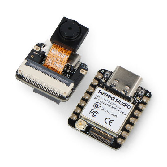
For this week, I have already worked with electrical components, that will be used in the final project. The microcontroller used was Seeed Xiao ESP32-S3 Sense. The reason for this choice is mainly it's size with addition for optional SD card memory and wireless comunication. The accelerometer used is still MPU-6050. Used display is OLED display 0.91" 128x32 I2C, this display is great for it's size and simplicity. Last but not least is the vibration motor module. The module made the implementation much easier, but due to it's size, I am planning to incorporate it to the custom pPCB for the final project using same vibration motor.


I have used I2C communication for both accelerometer and OLED display. For input sigal to vibration motor, pin D0 is used. Motor is controlled using PWM signal.

I have experience from the previous week, so for acceleration data input, nothing had to be changed, only acceleration in all 3 axis is now interpreted as 3D vector inside the microcontroller. I have tried to use u8g2lib library for OLED display, but I had to use Adafruit library instead as I was not able to make it run for the new display. For the vibration motor module, I have used 3,3 Volt power supply and input signal to the motor is PWM modulated from pin D0.
After that, I wanted to use FFT to detect frequencies of the signal and therefore be able to detect step frequency through frequency amplitudes. Unfortunately I wasn't able to get quality data at 100 Hz sampling rate and 128 samples (even that corresponded to 1.28 sec window of data which is quite a lot). Because of that, I decided to simplify peak detection. Firstly, data is stored in buffer and moving average is calculated over time to smoothen noisy signal. After that, slope of the signal is being calulated using two consecutive moving average acceleration and after detecting change of slope with moving average above/below threshold for high/low peak, time difference between current and pervious peak is written to the second circular buffer. Both of high and low peaks are computed to improve accuracy. To limit fluctuation of the frequency, frequency is computed from average of time differences in the buffer. After not detecting peaks for more than 2 seconds, frequency is set to zero and time difference buffer is cleared. The motor is set to increase vibrations with increased frequency. For detected of 1,2 steps per second, PWM signal is set to 140 which sets the motor to lowest possible working window. With increased frequency up to 3 steps per second, PWM signal is increased to maximum of 255. Final code looks like this:
    #include "I2Cdev.h"
    #include "MPU6050.h"
    #include "Adafruit_GFX.h"
    #include "Adafruit_SSD1306.h"

    // Display
    #define SCREEN_WIDTH 128
    #define SCREEN_HEIGHT 32
    #define OLED_RESET    -1
    #define SCREEN_ADDRESS 0x3C  // I2C address for SSD1306

    // Frequency detection
    #define SAMPLE_RATE 100
    #define MAX_THRESHOLD 20384
    #define MIN_THRESHOLD 12384
    #define MA_WINDOW_SIZE 10
    #define PEAK_WINDOW_SIZE 10
    #define CLEARANCE_DELAY 2000


    Adafruit_SSD1306 display(SCREEN_WIDTH, SCREEN_HEIGHT, &Wire, OLED_RESET);

    MPU6050 mpu; // MPU6050 address is 0x68
    hw_timer_t *timer = NULL;
    volatile bool flag = false;

    int MOTOR_PIN = D0;   // PWM pin for motor control
    int16_t ax, ay, az;
    bool blinkState;

    // MPU6050 offsets
    int16_t ax_offset = -3107;
    int16_t ay_offset = 1885;
    int16_t az_offset = 837;
    uint16_t currAccel;

    uint16_t maBuffer[MA_WINDOW_SIZE];
    unsigned int maIndex = 0;
    uint32_t maSum = 0;

    unsigned long peakBuffer[PEAK_WINDOW_SIZE] = {0};
    unsigned int peakIndex = 0;
    unsigned long periodSum = 0;
    unsigned long currTimeDiff = 0;

    unsigned long lastTime = 0;
    uint16_t prevAvg = 0;
    uint16_t currAvg = 0;
    volatile bool highPeakFlag = false;
    volatile bool computeAvg = false;

    void IRAM_ATTR onTimer() {
        flag = true;
    }

    void setup() {
        /*--Start I2C interface--*/
        #if I2CDEV_IMPLEMENTATION == I2CDEV_ARDUINO_WIRE
        Wire.begin();
        #elif I2CDEV_IMPLEMENTATION == I2CDEV_BUILTIN_FASTWIRE
        Fastwire::setup(400, true);
        #endif

        Serial.begin(115200);

        /*Initialize device and check connection*/
        Serial.println("Initializing MPU...");
        mpu.initialize();
        Serial.println("Testing MPU6050 connection...");

        if(mpu.testConnection() ==  false){
        Serial.println("MPU6050 connection failed");
        while(true);
        }
        else{
        Serial.println("MPU6050 connection successful");
        }
        mpu.setDLPFMode(5);

        Wire.begin(6, 7);  // For Seeed XIAO ESP32

        if (!display.begin(SSD1306_SWITCHCAPVCC, SCREEN_ADDRESS)) {
            Serial.println(F("SSD1306 allocation failed"));
            while (true);
        }
        display.clearDisplay();
        display.setTextSize(1);
        display.setTextColor(SSD1306_WHITE);
        display.setCursor(0, 0);
        display.print("Display Ready!");
        display.display();

        timer = timerBegin(0, 80, true);
        timerAttachInterrupt(timer, &onTimer, true);
        timerAlarmWrite(timer, 10000, true);  // 100 Hz sampling
        timerAlarmEnable(timer);

        /* Setting accelerometer offsets */
        Serial.println("Updating internal sensor offsets...\n");
        mpu.setXAccelOffset(ax_offset);
        mpu.setYAccelOffset(ay_offset);
        mpu.setZAccelOffset(az_offset);

        /*Configure board LED pin for output*/
        pinMode(LED_BUILTIN, OUTPUT);
        pinMode(MOTOR_PIN, OUTPUT);

        // Fill sample buffer
        for (int i = 0; i < MA_WINDOW_SIZE; i++) {
            mpu.getAcceleration(&ax, &ay, &az);
            currAccel = sqrt(ax * ax + ay * ay + az * az);
            maBuffer[i] = currAccel;
            maSum += currAccel;
            delay(10);
        }
        prevAvg = maSum / MA_WINDOW_SIZE;
    }

    void loop() {
        if (flag) {
        flag = false;
        unsigned long currentMillis = millis();
        mpu.getAcceleration(&ax, &ay, &az);

        // float ax_mps2 = ax / 16384.0 * 9.81;
        // float ay_mps2 = ay / 16384.0 * 9.81;
        // float az_mps2 = az / 16384.0 * 9.81;
        currAccel = sqrt(ax * ax + ay * ay + az * az);
        maSum = maSum - maBuffer[maIndex] + currAccel;
        maBuffer[maIndex] = currAccel;
        maIndex = (maIndex + 1) % MA_WINDOW_SIZE;
        currAvg = maSum / MA_WINDOW_SIZE;
        static int lastSlope = 0;
        int slope = currAvg - prevAvg;

        /* Detect peaks */
        if (lastSlope > 0 && slope < 0 && prevAvg > MAX_THRESHOLD && !highPeakFlag) {
            highPeakFlag = true;
            currTimeDiff = currentMillis - lastTime;
            periodSum = periodSum - peakBuffer[peakIndex] + currTimeDiff;
            peakBuffer[peakIndex] = currTimeDiff;
            if ((peakIndex + 1) % PEAK_WINDOW_SIZE == 0) {
            computeAvg = true;
            }
            peakIndex = (peakIndex + 1) % PEAK_WINDOW_SIZE;
            lastTime = currentMillis;
        } else if (lastSlope < 0 && slope > 0 && prevAvg < MIN_THRESHOLD && highPeakFlag) {
            highPeakFlag = false;
            currTimeDiff = currentMillis - lastTime;
            periodSum = periodSum - peakBuffer[peakIndex] + currTimeDiff;
            peakBuffer[peakIndex] = currTimeDiff;
            if ((peakIndex + 1) % PEAK_WINDOW_SIZE == 0) {
            computeAvg = true;
            }
            peakIndex = (peakIndex + 1) % PEAK_WINDOW_SIZE;
            lastTime = currentMillis;
        }

        /* Clear buffer when no peaks detected for CLEARANCE_DELAY ms */
        if (currentMillis - lastTime > CLEARANCE_DELAY) {
            computeAvg = false;
            periodSum = 0;
            memset(peakBuffer, 0, sizeof(peakBuffer));
            peakIndex = 0;
        }

        /* Compute frequency */
        float currentFreq = 0.0;
        if (computeAvg) {
            uint32_t periodAvg = (2 * periodSum) / PEAK_WINDOW_SIZE;
            currentFreq = 1000.0 / periodAvg;
            Serial.println("Period sum: " + String(periodSum) + "\t" +  "Period avg: " + String(periodAvg) + "\t" +  "Frequency: " + String(currentFreq));
        } else {
            currentFreq = 0.0;
        }

        lastSlope = slope;
        prevAvg = currAvg;
        // Serial.println(String(currentMillis / 1000.0) + "\t" +
        // String(ax) + "\t" +
        // String(ay) + "\t" +
        // String(az));

        /* Scale frequency to PWM signal for vibration motor */
        int pwmVal;
        if (currentFreq == 0.0) {
            pwmVal = 0;
        } else  {
            //pwmVal = (int)((currentFreq - 0.5) * (255.0-136.0) / (3.0 - 0.5) + 136.0);
            pwmVal = (int)((currentFreq - 1.2) * (255.0-140.0) / (3.0 - 1.2) + 140.0);
        }

        if (pwmVal > 255) {
            pwmVal = 255;
        } else if (pwmVal < 140 && pwmVal > 0) {
            pwmVal = 140;
        }else if (pwmVal < 0) {
            pwmVal = 0;
        }

        /* Write on display */
        display.clearDisplay();
        display.setCursor(0, 0);
        display.printf("Running frequency:\n");
        display.printf("%.2f steps per second\n", currentFreq);
        display.printf("PWM %d\n", pwmVal);
        display.display();


        analogWrite(MOTOR_PIN, pwmVal);
        // display.clearDisplay();
        // display.setCursor(0, 0);
        // display.printf("X: %.2f\n", ax_mps2);
        // display.printf("Y: %.2f\n", ay_mps2);
        // display.printf("Z: %.2f\n", az_mps2);
        // display.display();

        blinkState = !blinkState;
        digitalWrite(LED_BUILTIN, blinkState);
        }
    }
And circuit looks like this:

