Final project
For my final project, I decided to create a running bracelet that monitors pace. The main goal is to allow users to set their desired running pace in an app, which will also be part of the project. The bracelet provides feedback through vibrations—the further you deviate from the set pace, the stronger the vibrations.
Initial concept

The bracelet is designed to track the runner's pace using a GPS module. However, a potential drawback is that the GPS module may lack precision or perform poorly in crowded urban areas.
An alternative approach would be to use an accelerometer to track steps and estimate running pace based on step length. Step length can be approximated using the runner's height. Additionally, running data—such as accelerometer readings and pace information from apps like Strava could be used to interpolate the relationship between accelerometer data and running pace. However, a potential drawback of this method is inaccuracy due to incorrect step length calibration. A more effective solution could be to combine a GPS module with the accelerometer to improve accuracy and create an optimal tracking system.
The bracelet would consist of a rubber band and a removable electronic module, which could be inserted into the band, covering the charging port. The goal is to make the entire bracelet waterproof.
Final concept
Bracelet design
During the semester, my idea of final project slightly changed, but the key functionality prvailed. Firtsly, I have decided to add small OLED screen, that would inform the user about current running pace and set running pace. It could also display information about battery status. The initial idea was to control the bracelet purely by an app. That could be in some cases impractical, so the final design includes three buttons, one is used to turn on and off wireless comunication, needed for the mobile app, in order to save battery. The two other buttons are used to change the set running pace. The LED diodes stay in the final project, blue LED diode is used to indicate, whether the wireless BLE communication is tuerned on or off and the second one, red, indicates that the battery is below set threshold, 50%. The haptic feedback is then provided by two vibration motors.
Hardware
The soul of the project is the hardware, here is some information about the hardware used in the project.
Microcontroller
For the microcontroller, I have decided to use Xiao esp32 sense,
microcontroller with it's compact design, providing suitable option for wearable electronics. Even though the esp32 option doesn't have built-in accelerometer, it provides other
advantages such as built-in BLE communication and inner battery manager, providing easy way to power the device by an external LiPol battery with option to charge the battery via USB-C port.
The esp32 sense provides an additional peripheries, such as SD card slot and camera, I have used the SD card slot to save data for the bracelet calibration later in the project.
There is also an official Seeed studio wiki, which I have used a lot for my project.

Accelerometer
As an accelerometer, I have decided to use 3 axis gyroscope and accelerometer MPU-6050 in dedicated module . I have also tested another accelerometer, MPU-6500, which is much better, but the chosen accelerometer was sufficient for my project, as I only needed to examine absolute value of acceleration change, so the innacuracy of the accelerometer in values was not an issue.

Display
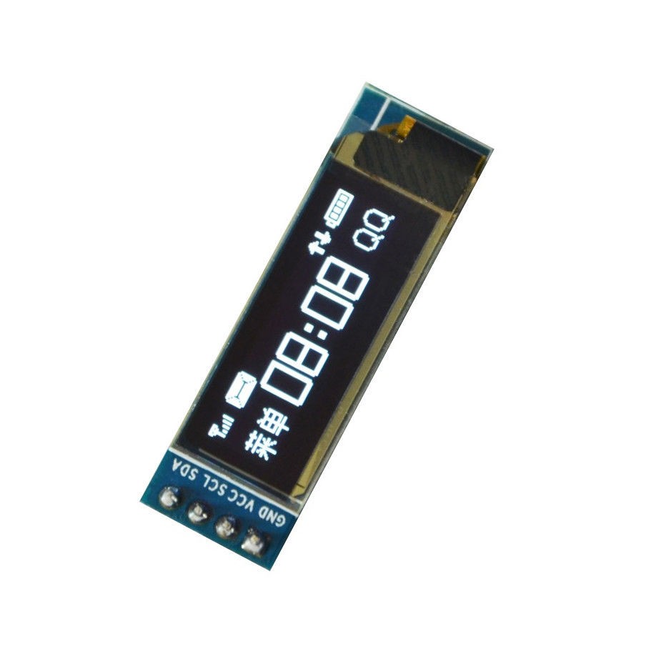
I wanted to use some small OLED display, that wouldn't cover much space and be as power efficient as possible. The one, I have used is this simple display.
Vibration motors
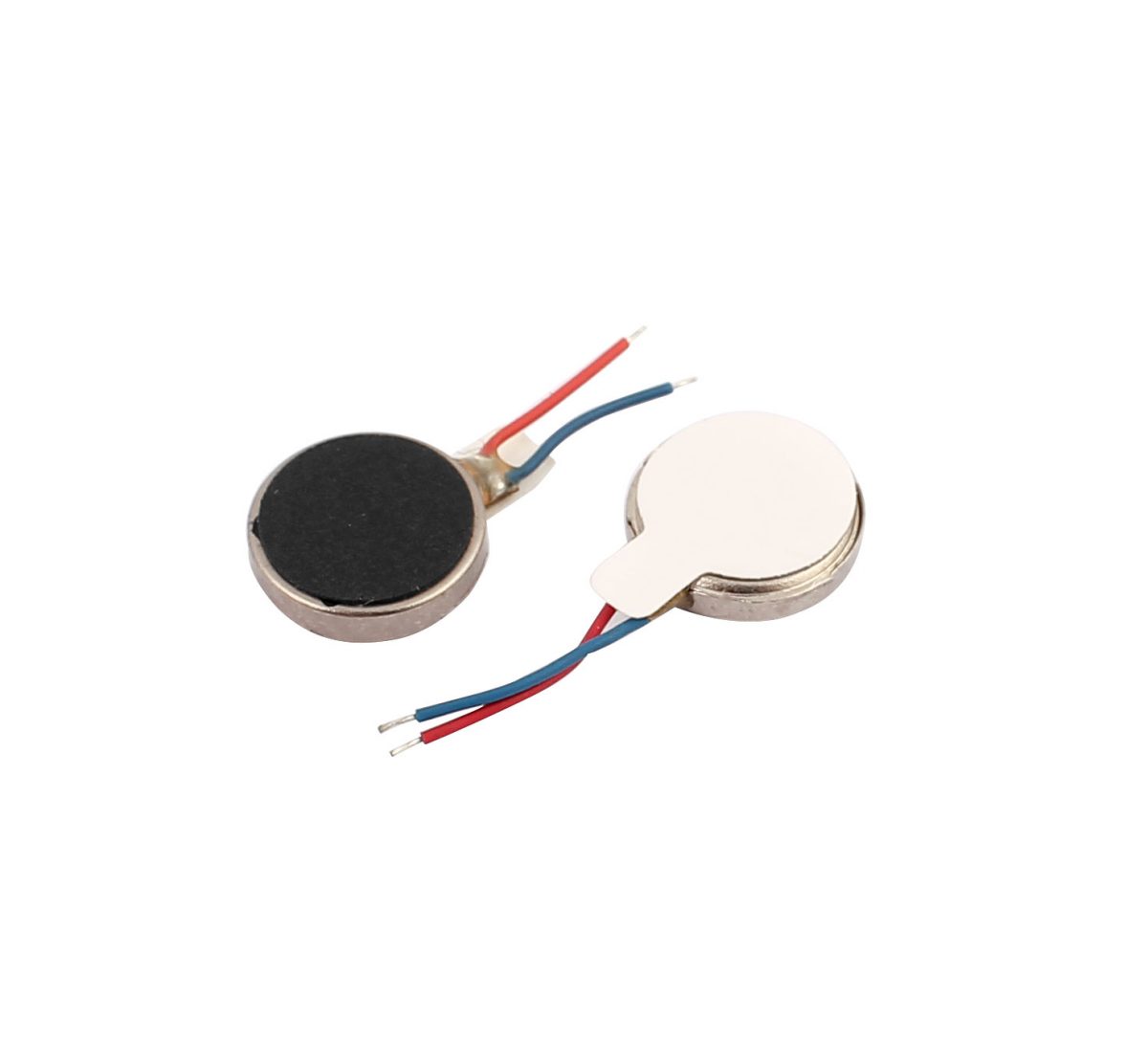
For the haptic feedback, I have used two 3V vibration motors. The inspiration for the motor implementation was this vibration motor module, that was used during the testing. I have tested the module circuit by multimeter and slightly adjusted the circuit to include two vibration motors instead of one. It would be easier to add the module to the bracelet, But I have decided to implement the circuit into my custom PCB to include two motors and save space.

Battery
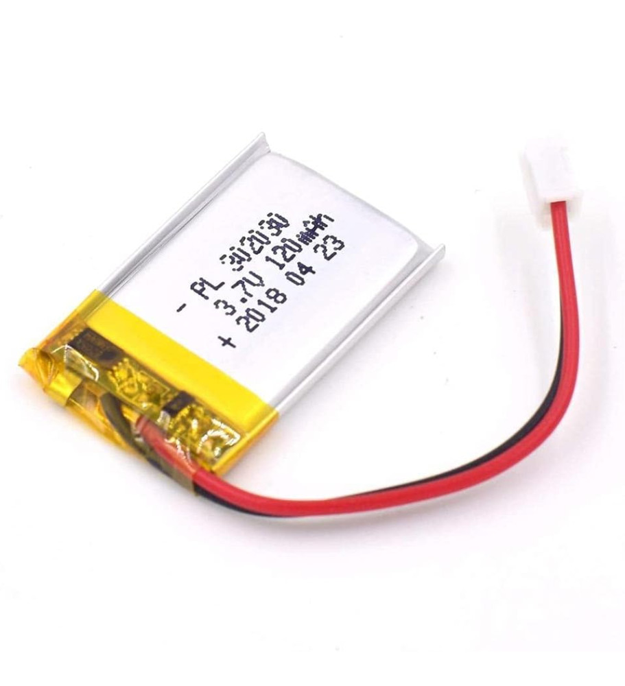
The battery was a tricky part of the project. It was fine line to balance between capacity and size, both crucial for my project. In the end, I have decided to use small 120 mAh 3.7 V LiPol battery with usable size.
Circuit design
To save as much space as possible, it was essential to design and create my own PCB for the project. Firstly, I have designed the electrical circuit. The whole design was created in Fusion 360 as I was suggested that it is the simplest way to prepare my design for manufacturing on the Carvera Makera CNC. It is fair to say that the battery isn't connected directly, but through switch and that the connection of the battery to the esp32 isn't visible as well, but it is connected through wires.

The Fusion 360 provides interface, that allows user to design the circuit schematic and corresponding PCB design, further exportable as 3D design. Because I was unable to find used modules in Fusion library,
I had to create my own, specifically the MPU-6050 module, OLED display, diode, capacitor, vibration motor input holes and button pads.
Each part can be created via New Electronic library function. Firstly, you need to create new component, then you must create New symbol and New Footprint, that matches physical component parameters. If wanted, 3D model can be added to the component.
A lot of 3D design are already made by the community, for example, I have used 3D model of the MPU-6050 module and OLED display from the GrabCAD. To add downloaded 3D design, simply upload the downloaded .step file to the project and use "Insert into current design" option.
Many schematics and footprints are also available from external libraries, the xiao esp32 schematic and footprint was taken from the official seeed studio library in Fusion 360 (althought it misses 3D model).
PCB design and manufacture
After that, the PCB design can be created by selecting "Switch to PCB document" option. I wanted to fit all the modules onto one side (with buttons and LED diodes) and all the SMD part to the other side, with battery, antenna and vibration motor also located there. With the modules being fixed to specific loaction, parameters of the CNC (needing to define own set of design rules as shown below) and small size of the PCB, it was quite tricky to design the PCB (at least for me, someone with no prior experience even with electrical circuit design).

Because of that, I ran into the problem of the routes crossing each other, so the only solution I have found was to create the PCB double sided as you can see in the design below.
To be able to create the double sided PCB, I needed to be able to precisely turn around the PCB, milled from the one side, so that the silhouette matches the one before turning around. To do this, I have
added two holes above each other, right in the middle of the PCB. Metal pins are then used to fix the placement of the PCB when turning around for milling the second side.
Then comes the manufacture, It was essential, to choose the right paths for milling, and right tools. The tools used were 0.6 mm and 1 mm corn mill with 1 mm drill.


Here, you can see automatically generated PCB 3D model provided by Fusion 360 functionality, as you can see, models for button and esp are missing, as mentioned before.
Soldering
I obviously forgot to take some photos of the soldering on the PCB, but it wasn't pretty image anyways. At least, here are some images of the final product.


Case design
After soldering and measuring all the parameters of the PCB, I have designed the case for the electronics. I tried many ideas on how to fit and fix the electronics on as little space as possible. The main problem I have encoutered was how to fix the PCB to the case. Because it is covered by the electronics on it's whole surface, I wasn't able to create any holes for screws. Also, many designs that would fix the PCB to the case resulted in an additional space needed, which wasn't ideal, so I have decided not to fix the PCB to the case, but make the inner space as tight as possible, so the electronics would not be able to move freely inside the case. This wa, I have designed two strap holder, that not only hold the rubber straps of the bracelet, but also push the electronics to the top of the case. They are also designed in a way, to leave room for the battery, antenna, vibration motors and the switch.

Here, you can see both disassabmled and assambled design.
Bracelet straps
For the straps, I have used the casting technique from the week 13 . Firstly, I have created 3D model of the strap (inspired by the Apple watch design) and it's mold in Fusion. Then, I have used Equinox 38 Medium and Dragon Skin 10 (Fast) for the material. Even though the dragon skin is more durable, it feels quite awkward for the strap, so I have decided to go with the Equinox 38 Medium silicone. The case is designed in a way, that the case with electronics holds together on its own and that the bottom part of the case can be easily detached to change the rubber straps.


Manufacture and assembly of the cover
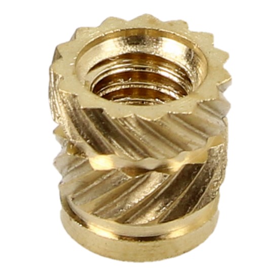
For the case, I have used the Průša 3D printer with 0.6 mm nozzle. The material, used for the case was PET-G. To asseble the parts, I have used threaded inserts, that can be easily inserted to the 3D printed parts and then easily screwed together, in this case by 2 mm screws. The final product can be seen below.


Software
The software is written entirely in C++. It is fair to say that I have used chatGPT in some cases as I don't have any experience with C++, but mostly, I tried to use code snippets from library examples, official documentation or other repositories. The project was written in the PlatformIO IDE, so the used libraries with example codes were accessed through this IDE.
Step detection
For the step detection, the MPU-6050 module is used. The Xiao esp32 sense and the accelerometer communicate via I2C protocol. The microcontroller reads data from the accelerometer and uses acceleration
in all three axis to calculate the absolute acceleration. When running, the absolute acceleration matches periodical sinusoidal signal with amplitude and offset, depending on the accelerometer.
By testing and reading the data, it is possible to detect signal peaks above certain threshold and determine the step frequency. The step frequency is calculated as moving average from the last 10 steps.
Given a step size, the step frequency can be easily converted to running pace (min/km). The step size can be approximated, but in this case, it is given by calibration mentioned later in the text.
Given a goal pace, the absolute difference is then converted to a PWM signal, that is used to control the vibration motors. The stronger the difference, the stronger the vibration.

The calibration of the accelerometer and used libraries are further explained on the week 6 page. Even thought an ESP32 Wroom is used, it is implemented the same way into the Xiao.
The detailed calculation of the step frequency and its conversion to the input to the vibration motor is explained on the week 7 page. Here, it is simplier, the vibration is not proportional
to the difference of set pace and current pace, but it is proportional to the step frequency.
OLED display
The implementation of the OLED display is quite simple. The Adafruit SSD1306 library is used, providing number of examples on how to use the display. In this cas, the display is used to show both running and set pace. There an also be seen the battery status in the right top corner, which is implemented simply by reading the voltage on the pin A0 and scaling it so it matches the battery voltage. Here, the voltage of 4.2 V indicates full batery with respect to 0 % corresponding to 3.3 V.
Wireless communication and an app development
For the wireless communication, I have decided to use built-in BLE, the esp32 host a server and the phone can be connected to the server via app. The app was made using Capacitor interface (for more, see week 10) and uploaded to my iPhone using Apples development interface. Unfortunately, Apple doesn't allow to keep the app running for more a week, so the app needs to be built again after the period of time. The mobile app is written in JavaScript. It allows to scan all bluetooth devices in the area, with addition to ignore all devices except service with given UUID, resulting in detecting only the bracelet. If the BLE server is turned on, the app can be connected and by clicking the "Get pace" button, it starts reading data, continuously sent by the bracelet. It is possible to set goal pace via slider in an app and send it to the bracelet to set goal pace in the bracelet. The JavaScript code can be seen below.
import { BleClient } from '@capacitor-community/bluetooth-le'
import { SplashScreen } from '@capacitor/splash-screen';

SplashScreen.hide();

function formatTempo(secPerKm) {
    if (!isFinite(secPerKm) || secPerKm <= 0) return "--:--";
    const minutes = Math.floor(secPerKm / 60);
    const seconds = Math.round(secPerKm % 60);
    return `${minutes}:${seconds.toString().padStart(2, '0')} min/km`;
  }

export async function scan() {
    try {
        await BleClient.initialize();
        await BleClient.requestLEScan({

        }, (result) =>{
            console.log('Scan result:', result);
        });

        setTimeout(async() => {
            await BleClient.stopLEScan();
            console.log('Scan stopped');
        }
        , 5000); // Stop scanning after 5 seconds
    } catch (error) {
        console.error('Error during scan:', error);
    }
}

let deviceObject;

export async function connect() {
    try {
        await BleClient.initialize();

         const device = await BleClient.requestDevice({
            services: ["9d7a19b5-33f4-4283-8036-f0af024c0dd6"],
         })

         await BleClient.connect(device.deviceId, (deviceId) => onDisconnect(deviceId));
         console.log('Connected to device:', device);
         deviceObject = device;

    } catch (error) {
        console.error('Error during scan:', error);
    }
}

const char1Value = document.getElementById('char1');

async function startListen() {
  await BleClient.startNotifications(
    deviceObject.deviceId,
    "9d7a19b5-33f4-4283-8036-f0af024c0dd6",
    "2288b759-4967-48dc-abcc-91e194acf8f6",
    (value) => {
      const freq = value.getFloat32(0, true); // <- read as Float32, little-endian
      console.log('Notification received:', freq);
      char1Value.innerHTML = formatTempo(freq);
    }
  );
}

let sliderValue;
const slider = document.getElementById('slider1');
const slider1Reading = document.getElementById('slider1-reading');
slider1Reading.innerHTML = formatTempo(slider.value);

async function writeData(value) {
    const bufferSize = 4; // 4 bytes for Float32
    const buffer = new ArrayBuffer(bufferSize);
    const dataView = new DataView(buffer);

    dataView.setFloat32(0, value, true); // Write float32 at offset 0, Little Endian

    await BleClient.write(
        deviceObject.deviceId,
        "9d7a19b5-33f4-4283-8036-f0af024c0dd6",
        "2698f81e-a4e7-4707-98ff-64d62fc8cb07",
        dataView
    );
}

slider.addEventListener('input', function () {
    sliderValue = parseFloat(this.value);
    slider1Reading.innerHTML = formatTempo(sliderValue);
  });

function onDisconnect(deviceId) {
    console.log('Disconnected from device:', deviceId);
}

const button1 = document.getElementById('button1');
button1.addEventListener('click', () => {
    connect();
});

const button2 = document.getElementById('button2');
button2.addEventListener('click', () => {
    startListen();
});

const button3 = document.getElementById('button3');
button3.addEventListener('click', () => {
    writeData(sliderValue)
});
The final code
Putting all together, the following code is used:
#include "I2Cdev.h" #include "MPU6050.h" #include#include #include #include #include #include // Display #define SCREEN_WIDTH 128 #define SCREEN_HEIGHT 32 #define OLED_RESET -1 #define SCREEN_ADDRESS 0x3C // I2C address for SSD1306 // Frequency detection #define SAMPLE_RATE 100 #define MAX_THRESHOLD 20384 #define MIN_THRESHOLD 12384 #define MA_WINDOW_SIZE 10 #define PEAK_WINDOW_SIZE 10 #define CLEARANCE_DELAY 2000 #define BLE_LED_PIN 3 #define BATTERY_LED_PIN 4 // BLE BLEServer* pServer = NULL; BLECharacteristic* pCharacteristic = NULL; BLECharacteristic* pCharacteristic_2 = NULL; BLEDescriptor *pDescr; BLE2902 *pBLE2902; bool bleEnabled = true; bool button44PrevState = HIGH; bool deviceConnected = false; bool oldDeviceConnected = false; // See the following for generating UUIDs: // https://www.uuidgenerator.net/ #define SERVICE_UUID "9d7a19b5-33f4-4283-8036-f0af024c0dd6" #define CHAR1_UUID "2288b759-4967-48dc-abcc-91e194acf8f6" #define CHAR2_UUID "2698f81e-a4e7-4707-98ff-64d62fc8cb07" // Variable to store the HTTP request String header; Adafruit_SSD1306 display(SCREEN_WIDTH, SCREEN_HEIGHT, &Wire, OLED_RESET); MPU6050 mpu; hw_timer_t *timer = NULL; volatile bool flag = false; int MOTOR_PIN = D1; // PWM pin for motor control int16_t ax, ay, az; bool blinkState; // MPU6050 offsets, different for each MPU-6050 module int16_t ax_offset = -3107; int16_t ay_offset = 1885; int16_t az_offset = 837; uint16_t currAccel; uint16_t maBuffer[MA_WINDOW_SIZE]; unsigned int maIndex = 0; uint32_t maSum = 0; unsigned long peakBuffer[PEAK_WINDOW_SIZE] = {0}; unsigned int peakIndex = 0; unsigned long periodSum = 0; unsigned long currTimeDiff = 0; unsigned long lastTime = 0; uint16_t prevAvg = 0; uint16_t currAvg = 0; volatile bool highPeakFlag = false; volatile bool computeAvg = false; float currentFreq = 0.0; float goalFreq = 360.0; float stepLen = 1.014764; // Step length, different for users unsigned long lastDebounceTime = 0; const unsigned long debounceDelay = 200; void IRAM_ATTR onTimer() { flag = true; } class MyServerCallbacks: public BLEServerCallbacks { void onConnect(BLEServer* pServer) { deviceConnected = true; }; void onDisconnect(BLEServer* pServer) { deviceConnected = false; } }; class CharacteristicCallBack: public BLECharacteristicCallbacks { void onWrite(BLECharacteristic *pChar) override { std::string value = pChar->getValue(); if (value.length() == 4) { memcpy(&goalFreq, value.data(), sizeof(float)); // copy bytes into float } } }; void setup() { /*--Start I2C interface--*/ #if I2CDEV_IMPLEMENTATION == I2CDEV_ARDUINO_WIRE Wire.begin(); #elif I2CDEV_IMPLEMENTATION == I2CDEV_BUILTIN_FASTWIRE Fastwire::setup(400, true); #endif Serial.begin(115200); delay(5000); /*Initialize device and check connection*/ Serial.println("Initializing MPU..."); mpu.initialize(); Serial.println("Testing MPU6050 connection..."); if(mpu.testConnection() == false){ Serial.println("MPU6050 connection failed"); while(true); } else{ Serial.println("MPU6050 connection successful"); } mpu.setDLPFMode(5); Wire.begin(6, 7); if (!display.begin(SSD1306_SWITCHCAPVCC, SCREEN_ADDRESS)) { Serial.println(F("SSD1306 allocation failed")); while (true); } display.clearDisplay(); display.setTextSize(1); display.setTextColor(SSD1306_WHITE); display.setCursor(0, 0); display.print("Display Ready!"); display.display(); timer = timerBegin(0, 80, true); timerAttachInterrupt(timer, &onTimer, true); timerAlarmWrite(timer, 10000, true); // 100 Hz sampling timerAlarmEnable(timer); mpu.setXAccelOffset(ax_offset); mpu.setYAccelOffset(ay_offset); mpu.setZAccelOffset(az_offset); /*Configure board LED pin for output*/ pinMode(8, INPUT_PULLUP); pinMode(7, INPUT_PULLUP); pinMode(44, INPUT_PULLUP); pinMode(LED_BUILTIN, OUTPUT); pinMode(A0, INPUT); pinMode(MOTOR_PIN, OUTPUT); pinMode(BLE_LED_PIN, OUTPUT); pinMode(BATTERY_LED_PIN, OUTPUT); digitalWrite(BLE_LED_PIN, HIGH); digitalWrite(BATTERY_LED_PIN, LOW); // Fill sample buffer for (int i = 0; i < MA_WINDOW_SIZE; i++) { mpu.getAcceleration(&ax, &ay, &az); currAccel = sqrt(ax * ax + ay * ay + az * az); maBuffer[i] = currAccel; maSum += currAccel; delay(10); } prevAvg = maSum / MA_WINDOW_SIZE; // BLE Device BLEDevice::init("ESP32"); // BLE Server pServer = BLEDevice::createServer(); pServer->setCallbacks(new MyServerCallbacks()); // BLE Service BLEService *pService = pServer->createService(SERVICE_UUID); // BLE Characteristic pCharacteristic = pService->createCharacteristic( CHAR1_UUID, BLECharacteristic::PROPERTY_NOTIFY ); pCharacteristic_2 = pService->createCharacteristic( CHAR2_UUID, BLECharacteristic::PROPERTY_READ | BLECharacteristic::PROPERTY_WRITE ); // BLE Descriptor pDescr = new BLEDescriptor((uint16_t)0x2901); pDescr->setValue("Running pace"); pCharacteristic->addDescriptor(pDescr); pBLE2902 = new BLE2902(); pBLE2902->setNotifications(true); pCharacteristic->addDescriptor(pBLE2902); pCharacteristic_2->addDescriptor(new BLE2902()); pCharacteristic_2->setCallbacks(new CharacteristicCallBack()); pService->start(); // Start advertising BLEAdvertising *pAdvertising = BLEDevice::getAdvertising(); pAdvertising->addServiceUUID(SERVICE_UUID); pAdvertising->setScanResponse(false); pAdvertising->setMinPreferred(0x0); // set value to 0x00 to not advertise this parameter BLEDevice::startAdvertising(); Serial.println("Waiting a client connection to notify..."); } void loop() { if (flag) { flag = false; unsigned long currentMillis = millis(); mpu.getAcceleration(&ax, &ay, &az); currAccel = sqrt(ax * ax + ay * ay + az * az); maSum = maSum - maBuffer[maIndex] + currAccel; maBuffer[maIndex] = currAccel; maIndex = (maIndex + 1) % MA_WINDOW_SIZE; currAvg = maSum / MA_WINDOW_SIZE; static int lastSlope = 0; int slope = currAvg - prevAvg; if (digitalRead(8) == LOW) { goalFreq += 1; if (goalFreq > 600.0) goalFreq = 600.0; delay(150); } if (digitalRead(7) == LOW) { goalFreq -= 1; if (goalFreq < 180.0) goalFreq = 180.0; delay(150); } // Toggle BLE bool button44State = digitalRead(44); if (button44PrevState == HIGH && button44State == LOW && millis() - lastDebounceTime > debounceDelay) { bleEnabled = !bleEnabled; lastDebounceTime = millis(); if (bleEnabled) { BLEDevice::startAdvertising(); digitalWrite(BLE_LED_PIN, HIGH); } else { if (deviceConnected) { pServer->disconnect(0); } BLEDevice::getAdvertising()->stop(); digitalWrite(BLE_LED_PIN, LOW); } } button44PrevState = button44State; /* Detect peaks */ if (lastSlope > 0 && slope < 0 && prevAvg > MAX_THRESHOLD && !highPeakFlag) { highPeakFlag = true; currTimeDiff = currentMillis - lastTime; periodSum = periodSum - peakBuffer[peakIndex] + currTimeDiff; peakBuffer[peakIndex] = currTimeDiff; if ((peakIndex + 1) % PEAK_WINDOW_SIZE == 0) { computeAvg = true; } peakIndex = (peakIndex + 1) % PEAK_WINDOW_SIZE; lastTime = currentMillis; } else if (lastSlope < 0 && slope > 0 && prevAvg < MIN_THRESHOLD && highPeakFlag) { highPeakFlag = false; currTimeDiff = currentMillis - lastTime; periodSum = periodSum - peakBuffer[peakIndex] + currTimeDiff; peakBuffer[peakIndex] = currTimeDiff; if ((peakIndex + 1) % PEAK_WINDOW_SIZE == 0) { computeAvg = true; } peakIndex = (peakIndex + 1) % PEAK_WINDOW_SIZE; lastTime = currentMillis; } /* Clear buffer when no peaks detected for CLEARANCE_DELAY ms */ if (currentMillis - lastTime > CLEARANCE_DELAY) { computeAvg = false; periodSum = 0; memset(peakBuffer, 0, sizeof(peakBuffer)); peakIndex = 0; } /* Compute frequency */ if (computeAvg) { uint32_t periodAvg = (2 * periodSum) / PEAK_WINDOW_SIZE; currentFreq = 1000.0 / periodAvg; Serial.println("Period sum: " + String(periodSum) + "\t" + "Period avg: " + String(periodAvg) + "\t" + "Frequency: " + String(currentFreq)); } else { currentFreq = 0.0; } lastSlope = slope; prevAvg = currAvg; // Convert step frequency to the pace float tempo_current_sec = currentFreq > 0 ? 1000.0 / (currentFreq *stepLen) : 0.0; float tempo_goal_sec = goalFreq; int tempo_current_min = tempo_current_sec / 60; int tempo_current_sec_rem = (int)tempo_current_sec % 60; int tempo_goal_min = tempo_goal_sec / 60; int tempo_goal_sec_rem = (int)tempo_goal_sec % 60; float tempoDiff = abs(tempo_current_sec - goalFreq); int pwmVal; if (currentFreq == 0.0) { pwmVal = 0; } else { if (tempoDiff > 3.0) { pwmVal = (int)((tempoDiff - 3.0) * (255.0 - 140.0) / (60.0 - 3.0) + 140.0); } else { pwmVal = 0; } } if (pwmVal > 255) { pwmVal = 255; } else if (pwmVal > 0 && pwmVal < 140) { pwmVal = 140; } else if (pwmVal < 0) { pwmVal = 0; } // Battery voltage measurement uint32_t Vbatt = 0; for (int i = 0; i < 16; i++) { Vbatt += analogReadMilliVolts(A0); // ADC with correction } float Vbattf = 2 * Vbatt / 16 / 1000.0; // adjust for 1/2 voltage divider, convert mV to V float percentage = 0.0; if (Vbattf >= 4.2) percentage = 100.0; else if (Vbattf <= 3.3) percentage = 0.0; else { percentage = (Vbattf - 3.3) / (4.2 - 3.3) * 100.0; } // LED indicator if (percentage < 50.0) { digitalWrite(BATTERY_LED_PIN, HIGH); } else { digitalWrite(BATTERY_LED_PIN, LOW); } /* Write on display */ display.clearDisplay(); display.setCursor(0, 0); display.printf("Current Tempo:\n"); if (currentFreq > 0.0) { display.printf("%d:%02d min/km\n", tempo_current_min, tempo_current_sec_rem); } else { display.print("--:-- min/km\n"); } display.printf("Goal Tempo:\n"); display.printf("%d:%02d min/km\n", tempo_goal_min, tempo_goal_sec_rem); // Format battery percentage text char battStr[8]; snprintf(battStr, sizeof(battStr), "%.0f%%", percentage); // Draw battery percentage int16_t x = SCREEN_WIDTH - 6 * strlen(battStr); int16_t y = 0; display.setCursor(x, y); display.print(battStr); display.display(); analogWrite(MOTOR_PIN, pwmVal); // Run vibration motos if (deviceConnected) { pCharacteristic->setValue((uint8_t*)&tempo_current_sec, sizeof(tempo_current_sec)); pCharacteristic->notify(); } } }
Calibration
To get running pace, step frequency needs to be converted from step/s to min/km. By multiplying step frequency with step length, the speed m/s can be calcluated, which can be converted to the wanted min/km.
The step length varies user to user. It could me measure, or approximated by the height of the user, but I have decided to calibrate it for my eight more precisely. I have decided to create my own circuit, that matches
the one used in the bracelet, but without all unnecesary parts, so only the accelerometer stays. I have also slightly adjusted the code for both bracelet and an app.
The idea was to run on a treadmill, where the running pace can be set precisely. While running, the step frequency is recorded to the SD card with running pace set from the treadmill.


The code is then adjusted in a way that writing to an SD card is enabled. The bracelet then connects to the app and app via the app, the current running pace is sent to the bracelet and written together with corresponding step frequency to a CSV file. The adjusted code for an app and bracelet are below.
#include "FS.h" #include "SD.h" #include "SPI.h" #include#include #include #include #include "MPU6050.h" // Peak detection #define SAMPLE_RATE 100 #define MAX_THRESHOLD 20384 #define MIN_THRESHOLD 12384 #define MA_WINDOW_SIZE 10 #define PEAK_WINDOW_SIZE 10 #define CLEARANCE_DELAY 2000 // BLE #define SERVICE_UUID "9d7a19b5-33f4-4283-8036-f0af024c0dd6" #define CHAR1_UUID "2288b759-4967-48dc-abcc-91e194acf8f6" #define CHAR2_UUID "2698f81e-a4e7-4707-98ff-64d62fc8cb07" BLEServer* pServer = NULL; BLECharacteristic* pCharacteristic = NULL; BLECharacteristic* pCharacteristic_2 = NULL; BLEDescriptor *pDescr; BLE2902 *pBLE2902; bool deviceConnected = false; bool oldDeviceConnected = false; // MPU6050 MPU6050 mpu; int16_t ax_offset = -3107; int16_t ay_offset = 1885; int16_t az_offset = 837; uint16_t currAccel; int16_t ax, ay, az; // timer hw_timer_t *timer = NULL; // Moving average uint16_t maBuffer[MA_WINDOW_SIZE]; unsigned int maIndex = 0; uint32_t maSum = 0; unsigned long peakBuffer[PEAK_WINDOW_SIZE] = {0}; unsigned int peakIndex = 0; unsigned long periodSum = 0; unsigned long currTimeDiff = 0; unsigned long lastTime = 0; uint16_t prevAvg = 0; uint16_t currAvg = 0; volatile bool highPeakFlag = false; volatile bool computeAvg = false; float currentFreq = 0.0; volatile bool writeData = false; volatile bool flag = false; float currTempo = 0.0; bool blinkState; // ----------------------------------- Functions and callbacks ----------------------------------- void IRAM_ATTR onTimer() { flag = true; } class MyServerCallbacks: public BLEServerCallbacks { void onConnect(BLEServer* pServer) { deviceConnected = true; }; void onDisconnect(BLEServer* pServer) { deviceConnected = false; } }; class CharacteristicCallBack: public BLECharacteristicCallbacks { void onWrite(BLECharacteristic *pChar) override { std::string value = pChar->getValue(); if (value.length() == 4) { // float32 is exactly 4 bytes writeData = true; memcpy(&currTempo, value.data(), sizeof(float)); // copy bytes into float Serial.println(currTempo, 4); // show 4 decimals } } }; void listDir(fs::FS &fs, const char * dirname, uint8_t levels){ Serial.printf("Listing directory: %s\n", dirname); File root = fs.open(dirname); if(!root){ Serial.println("Failed to open directory"); return; } if(!root.isDirectory()){ Serial.println("Not a directory"); return; } File file = root.openNextFile(); while(file){ if(file.isDirectory()){ Serial.print(" DIR : "); Serial.println(file.name()); if(levels){ listDir(fs, file.path(), levels -1); } } else { Serial.print(" FILE: "); Serial.print(file.name()); Serial.print(" SIZE: "); Serial.println(file.size()); } file = root.openNextFile(); } } void createDir(fs::FS &fs, const char * path){ Serial.printf("Creating Dir: %s\n", path); if(fs.mkdir(path)){ Serial.println("Dir created"); } else { Serial.println("mkdir failed"); } } void removeDir(fs::FS &fs, const char * path){ Serial.printf("Removing Dir: %s\n", path); if(fs.rmdir(path)){ Serial.println("Dir removed"); } else { Serial.println("rmdir failed"); } } void readFile(fs::FS &fs, const char * path){ Serial.printf("Reading file: %s\n", path); File file = fs.open(path); if(!file){ Serial.println("Failed to open file for reading"); return; } Serial.print("Read from file: "); while(file.available()){ Serial.write(file.read()); } file.close(); } void writeFile(fs::FS &fs, const char * path, const char * message){ Serial.printf("Writing file: %s\n", path); File file = fs.open(path, FILE_WRITE); if(!file){ Serial.println("Failed to open file for writing"); return; } if(file.print(message)){ Serial.println("File written"); } else { Serial.println("Write failed"); } file.close(); } void appendFile(fs::FS &fs, const char * path, const char * message){ Serial.printf("Appending to file: %s\n", path); File file = fs.open(path, FILE_APPEND); if(!file){ Serial.println("Failed to open file for appending"); return; } if(file.print(message)){ Serial.println("Message appended"); } else { Serial.println("Append failed"); } file.close(); } void renameFile(fs::FS &fs, const char * path1, const char * path2){ Serial.printf("Renaming file %s to %s\n", path1, path2); if (fs.rename(path1, path2)) { Serial.println("File renamed"); } else { Serial.println("Rename failed"); } } void deleteFile(fs::FS &fs, const char * path){ Serial.printf("Deleting file: %s\n", path); if(fs.remove(path)){ Serial.println("File deleted"); } else { Serial.println("Delete failed"); } } void testFileIO(fs::FS &fs, const char * path){ File file = fs.open(path); static uint8_t buf[512]; size_t len = 0; uint32_t start = millis(); uint32_t end = start; if(file){ len = file.size(); size_t flen = len; start = millis(); while(len){ size_t toRead = len; if(toRead > 512){ toRead = 512; } file.read(buf, toRead); len -= toRead; } end = millis() - start; Serial.printf("%u bytes read for %u ms\n", flen, end); file.close(); } else { Serial.println("Failed to open file for reading"); } file = fs.open(path, FILE_WRITE); if(!file){ Serial.println("Failed to open file for writing"); return; } size_t i; start = millis(); for(i=0; i<2048; i++){ file.write(buf, 512); } end = millis() - start; Serial.printf("%u bytes written for %u ms\n", 2048 * 512, end); file.close(); } /* -------------------------------------------------- Setup -------------------------------------------------- */ void setup(){ Serial.begin(115200); #if I2CDEV_IMPLEMENTATION == I2CDEV_ARDUINO_WIRE Wire.begin(); #elif I2CDEV_IMPLEMENTATION == I2CDEV_BUILTIN_FASTWIRE Fastwire::setup(400, true); #endif delay(5000); /*Initialize device and check connection*/ Serial.println("Initializing MPU..."); mpu.initialize(); Serial.println("Testing MPU6050 connection..."); if(mpu.testConnection() == false){ Serial.println("MPU6050 connection failed"); while(true); } else{ Serial.println("MPU6050 connection successful"); } mpu.setDLPFMode(5); // SD card while(!Serial); if(!SD.begin(21)){ Serial.println("Card Mount Failed"); return; } uint8_t cardType = SD.cardType(); if(cardType == CARD_NONE){ Serial.println("No SD card attached"); return; } timer = timerBegin(0, 80, true); timerAttachInterrupt(timer, &onTimer, true); timerAlarmWrite(timer, 10000, true); // 100 Hz sampling timerAlarmEnable(timer); mpu.setXAccelOffset(ax_offset); mpu.setYAccelOffset(ay_offset); mpu.setZAccelOffset(az_offset); // Fill sample buffer for (int i = 0; i < MA_WINDOW_SIZE; i++) { mpu.getAcceleration(&ax, &ay, &az); currAccel = sqrt(ax * ax + ay * ay + az * az); maBuffer[i] = currAccel; maSum += currAccel; delay(10); } prevAvg = maSum / MA_WINDOW_SIZE; // Create the BLE Device BLEDevice::init("ESP32"); // Create the BLE Server pServer = BLEDevice::createServer(); pServer->setCallbacks(new MyServerCallbacks()); // Create the BLE Service BLEService *pService = pServer->createService(SERVICE_UUID); // Create a BLE Characteristic pCharacteristic = pService->createCharacteristic( CHAR1_UUID, BLECharacteristic::PROPERTY_NOTIFY ); // Phone to esp pCharacteristic_2 = pService->createCharacteristic( CHAR2_UUID, BLECharacteristic::PROPERTY_READ | BLECharacteristic::PROPERTY_WRITE ); // Create a BLE Descriptor pDescr = new BLEDescriptor((uint16_t)0x2901); pDescr->setValue("Running tempo data"); pCharacteristic->addDescriptor(pDescr); pBLE2902 = new BLE2902(); pBLE2902->setNotifications(true); // Add all Descriptors here pCharacteristic->addDescriptor(pBLE2902); pCharacteristic_2->addDescriptor(new BLE2902()); // After defining the desriptors, set the callback functions pCharacteristic_2->setCallbacks(new CharacteristicCallBack()); // Start the service pService->start(); // Start advertising BLEAdvertising *pAdvertising = BLEDevice::getAdvertising(); pAdvertising->addServiceUUID(SERVICE_UUID); pAdvertising->setScanResponse(false); pAdvertising->setMinPreferred(0x0); // set value to 0x00 to not advertise this parameter BLEDevice::startAdvertising(); Serial.println("Waiting a client connection to notify..."); File file = SD.open("/data.csv", FILE_WRITE); if (file) { file.println("Time(ms),Frequency(Hz),Tempo(min/km)"); file.close(); Serial.println("Log file initialized"); } else { Serial.println("Failed to initialize log file"); } pinMode(LED_BUILTIN, OUTPUT); } uint16_t computeMovingAverage(uint16_t newValue) { maSum = maSum - maBuffer[maIndex] + newValue; maBuffer[maIndex] = newValue; maIndex = (maIndex + 1) % MA_WINDOW_SIZE; return maSum / MA_WINDOW_SIZE; } // ----------------------------------- Loop ----------------------------------- void loop(){ if (flag) { flag = false; unsigned long currentMillis = millis(); mpu.getAcceleration(&ax, &ay, &az); currAccel = sqrt(ax * ax + ay * ay + az * az); currAvg = computeMovingAverage(currAccel); static int lastSlope = 0; int slope = currAvg - prevAvg; // Peak detection if (lastSlope > 0 && slope < 0 && prevAvg > MAX_THRESHOLD && !highPeakFlag) { highPeakFlag = true; currTimeDiff = currentMillis - lastTime; periodSum = periodSum - peakBuffer[peakIndex] + currTimeDiff; peakBuffer[peakIndex] = currTimeDiff; if ((peakIndex + 1) % PEAK_WINDOW_SIZE == 0) { computeAvg = true; } peakIndex = (peakIndex + 1) % PEAK_WINDOW_SIZE; lastTime = currentMillis; } else if (lastSlope < 0 && slope > 0 && prevAvg < MIN_THRESHOLD && highPeakFlag) { highPeakFlag = false; currTimeDiff = currentMillis - lastTime; periodSum = periodSum - peakBuffer[peakIndex] + currTimeDiff; peakBuffer[peakIndex] = currTimeDiff; if ((peakIndex + 1) % PEAK_WINDOW_SIZE == 0) { computeAvg = true; } peakIndex = (peakIndex + 1) % PEAK_WINDOW_SIZE; lastTime = currentMillis; } // Clear buffer when no peaks detected if (currentMillis - lastTime > CLEARANCE_DELAY) { computeAvg = false; periodSum = 0; memset(peakBuffer, 0, sizeof(peakBuffer)); peakIndex = 0; } // Compute frequency if (computeAvg) { uint32_t periodAvg = (2 * periodSum) / PEAK_WINDOW_SIZE; currentFreq = 1000.0 / periodAvg; Serial.println("Frequency: " + String(currentFreq)); } else { currentFreq = 0.0; } if (writeData) { File file = SD.open("/data.csv", FILE_APPEND); if (file) { file.printf("%lu,%.3f,%.3f\n", millis(), currentFreq, currTempo); Serial.print("Written: "); Serial.printf("%lu,%.3f\n", millis(), currentFreq); Serial.println("Tempo: " + String(currTempo)); file.close(); } else { Serial.println("Failed to append to log file"); } } lastSlope = slope; prevAvg = currAvg; if (deviceConnected) { pCharacteristic->setValue((uint8_t*)¤tFreq, sizeof(currentFreq)); pCharacteristic->notify(); } } }
import { BleClient } from '@capacitor-community/bluetooth-le'
import { SplashScreen } from '@capacitor/splash-screen';

SplashScreen.hide();

export async function scan() {
    try {
        await BleClient.initialize();
        await BleClient.requestLEScan({

        }, (result) =>{
            console.log('Scan result:', result);
        });

        setTimeout(async() => {
            await BleClient.stopLEScan();
            console.log('Scan stopped');
        }
        , 5000); // Stop scanning after 5 seconds
    } catch (error) {
        console.error('Error during scan:', error);
    }
}

let deviceObject;

export async function connect() {
    try {
        await BleClient.initialize();

            const device = await BleClient.requestDevice({
            services: ["9d7a19b5-33f4-4283-8036-f0af024c0dd6"],
            })

            await BleClient.connect(device.deviceId, (deviceId) => onDisconnect(deviceId));
            console.log('Connected to device:', device);
            deviceObject = device;

    } catch (error) {
        console.error('Error during scan:', error);
    }
}

const char1Value = document.getElementById('char1');

async function startListen() {
    await BleClient.startNotifications(
    deviceObject.deviceId,
    "9d7a19b5-33f4-4283-8036-f0af024c0dd6",
    "2288b759-4967-48dc-abcc-91e194acf8f6",
    (value) => {
        const freq = value.getFloat32(0, true); // <- read as Float32, little-endian
        console.log('Notification received:', freq);
        char1Value.innerHTML = freq.toFixed(2); // show two decimal places
    }
    );
}


let currTempo = 450; // Default tempo

const slider1Reading = document.getElementById('slider1-reading');
slider1Reading.innerHTML = currTempo.toFixed(2);

document.getElementById('tempo-increase').addEventListener('click', () => {
    currTempo = Math.min(currTempo + 1, 480);
    slider1Reading.innerHTML = currTempo.toFixed(2);
    console.log('Tempo increased:', currTempo.toFixed(2));
});

document.getElementById('tempo-decrease').addEventListener('click', () => {
    currTempo = Math.max(currTempo - 1, 240);
    slider1Reading.innerHTML = currTempo.toFixed(2);
    console.log('Tempo decreased:', currTempo.toFixed(2));
});

async function writeData(value) {
    const bufferSize = 4; // 4 bytes for Float32
    const buffer = new ArrayBuffer(bufferSize);
    const dataView = new DataView(buffer);

    dataView.setFloat32(0, value, true); // Write float32 at offset 0, Little Endian

    await BleClient.write(
        deviceObject.deviceId,
        "9d7a19b5-33f4-4283-8036-f0af024c0dd6",
        "2698f81e-a4e7-4707-98ff-64d62fc8cb07",
        dataView
    );
}

function onDisconnect(deviceId) {
    console.log('Disconnected from device:', deviceId);
}

const button1 = document.getElementById('button1');
button1.addEventListener('click', () => {
    connect();
});

const button2 = document.getElementById('button2');
button2.addEventListener('click', () => {
    startListen();
});

const button3 = document.getElementById('button3');
button3.addEventListener('click', () => {
    writeData(currTempo)
});
The data was then used to find optimal step length using simple python script with scipy functionality minimize.
import pandas as pd
import numpy as np
import matplotlib.pyplot as plt
from scipy.optimize import minimize

def load_data(file_path):
    df = pd.read_csv(file_path)
    df = df.dropna()
    df = df[df['Frequency(Hz)'] != 0]
    return df


def average_by_tempo(df):
    grouped = df.groupby('Tempo(min/km)')['Frequency(Hz)'].mean().reset_index()
    grouped = grouped.rename(columns={'Frequency(Hz)': 'Frequency_avg'})
    grouped = grouped[grouped['Frequency_avg'] != 0]  # Skip 0 avg frequencies
    return grouped

def loss_function(l, data):
    l = l[0]
    predicted_tempo = l / (data['Frequency_avg']/1000)
    return np.mean((predicted_tempo - data['Tempo(min/km)'])**2)


# Optimize l
def optimize_l(data):
    result = minimize(loss_function, x0=[1.0], args=(data,), bounds=[(1e-6, None)])
    return result.x[0]

# Plot results
def plot_data(data, optimal_l):
    freq = data['Frequency_avg']
    tempo = data['Tempo(min/km)']

    freq_range = np.linspace(freq.min(), freq.max(), 100)
    predicted_tempo_line = optimal_l / (freq_range / 1000)

    plt.figure(figsize=(10, 6))
    plt.scatter(freq, tempo, label='Averaged Data Points', color='blue')
    plt.plot(freq_range, predicted_tempo_line, label=f'Fitted Line (l = {optimal_l:.4f})', color='red')
    plt.xlabel('Step Frequency (Hz)')
    plt.ylabel('Tempo (min/km)')
    plt.title('Step Frequency vs Tempo with Fitted Model')
    plt.legend()
    plt.grid(True)
    plt.tight_layout()
    plt.show()

def main():
    file_path = 'data2.csv'
    df = load_data(file_path)
    grouped_data = average_by_tempo(df)
    optimal_l = optimize_l(grouped_data)
    print(f"Optimal l: {optimal_l:.6f}")
    plot_data(grouped_data, optimal_l)

if __name__ == '__main__':
    main()

According to calibrated data, my step length was 1.0148 m, therefore used in the bracelet pace calculations.
Results and personal notes
I was able to successfully reach my goal of creating the bracelet. The result is bigger than expected, but is still borderline wearable. On the bright side, the final project turned out to be
more complex than initial design, with the buttons, battery manager and OLED display. The software and hardware work well together and I haven't encountered any bugs or issues when trying out the bracelet.
To share some personal experience, I have to say that I would think twice before deciding to make small wearable electronics again. As someone with no previous experience with pretty much anything, from electronic design to soldering,
it was quite challenging to make the final product with limited resources, that would satisfy all the functionalities I wanted and still be wearable as a bracelet. The soldering on the small space crowded with modules was probably the
most challenging part. In the end, everything worked out well and I am happy with the result. I have learned a lot in this project, such as the electronic design, PCB design, soldering, programming, 3D design and printing, wireless BLE communication, app development and much more.
This is something I am the most happy about, with addition that despite time pressure from the bachelor thesis, I was able to finish the project.